xBee wireless communication modules + Arduino
xBee are inexpensive radio modules that provide I/O and serial communications. My experience is with the 802.15.4 protocol modules.
Troubleshooting Setup
Initial parameters:
CH = 0xC
CE = 0x0
BD = 0x3
RO = 0x3
AP = 0x0 transparent mode
IU = 1 i/o to UART enabled. THIS IS IMPORTANT
IR = 0x14
P0 = 0x1
IA = 0xFFFF
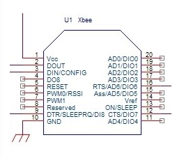
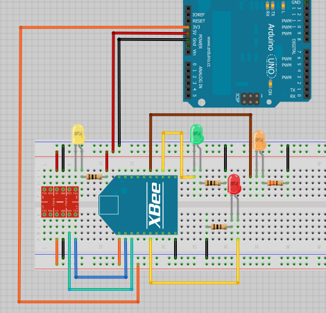
The LED connected to pin 15 (Associate Indicator) flashes during XBee communication except when in AT mode.
When uploading a sketch to the remote XBee connected to an Arduino, you will see the RX LED blink several times at the end of the sequence.
Loopback Tests
XBee local/remote loopback serial tests. Set both XBees to transparent mode (AP=0). Setup a wired loopback on the remote XBee by connecting the TX and RX pins (2 & 3) together .
Simple serial mode test. On the local XBee connected to X-CTU, go to the terminal and type any characters. The characters should be repeated in red, indicating serial communication with the remote XBee. While typing, the LED on remote XBee pin #6 (RSSI) should illuminate.

Confirm node discovery. In X-CTU, go to the terminal and enter AT command mode (+++). Then enter the Node Discover command "ATND". It will report all modules on its current operating channel and PAN ID. You should see the remote node address and serial number. If the remote is not powered, you will not see any response to the command. The remote Xbee RSSI LED should illuminate briefly.

Perform a range test. Try the Range Test in X-CTU. Check the RSSI checkbox. NOTE: If RO = 0, and the BD is low (BD = 3, 9600 baud), then this will NOT work. Change RO = 3. The RSSI LED in pin 6 will illuminate.
Do you need help developing or customizing a IoT product for your needs? Send me an email requesting a free one hour phone / web share consultation.
The information presented on this website is for the author's use only. Use of this information by anyone other than the author is offered as guidelines and non-professional advice only. No liability is assumed by the author or this web site.




.png)


.png)




.png)
.png)


.png)


.png)

.png)
.jpg)

.png)


.png)

.jpg)


.png)
