NTC Thermistor
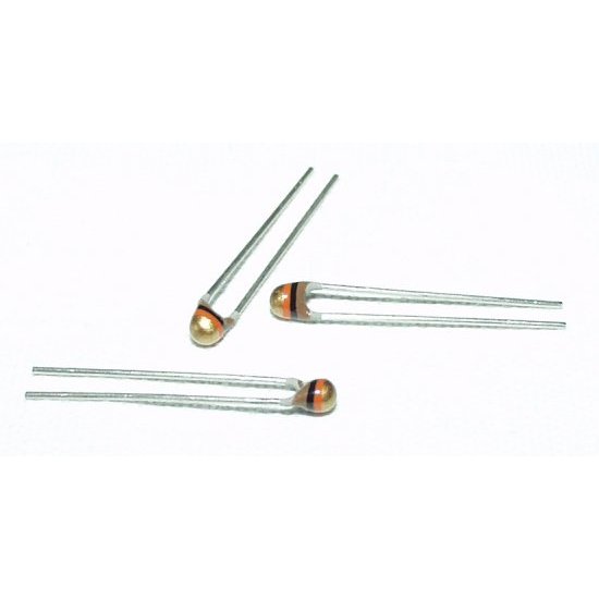
Thermistors are simple analog sensors that output a change in resistance in proportion to the ambient temperature. A Negative Temperature Coefficient (NTC) thermistor resistance decreases with an increase in temperature.
Components
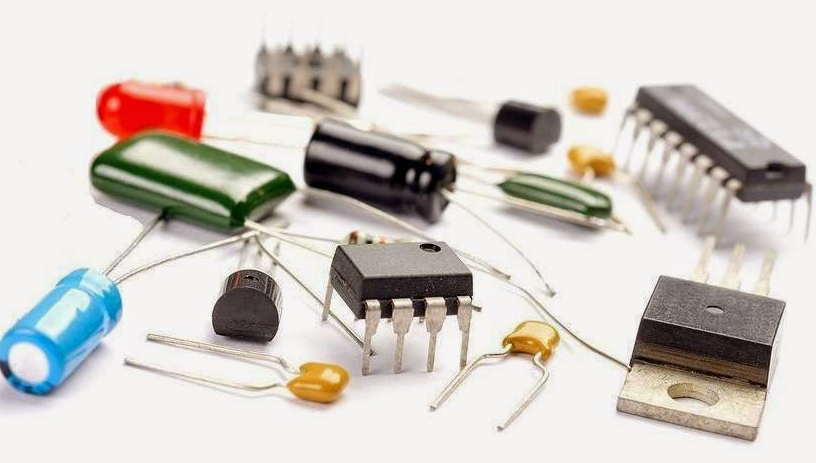
You can purchase the thermistor used in this example from either SparkFun or Mouser. Datasheet for the thermistor. The circuit and the code can be adapted for any NTC thermistor.
SparkFun SEN-00250
Mouser P/N 474-SEN-00250
Vishay part #: NTCLE100E3103JB0
Circuit
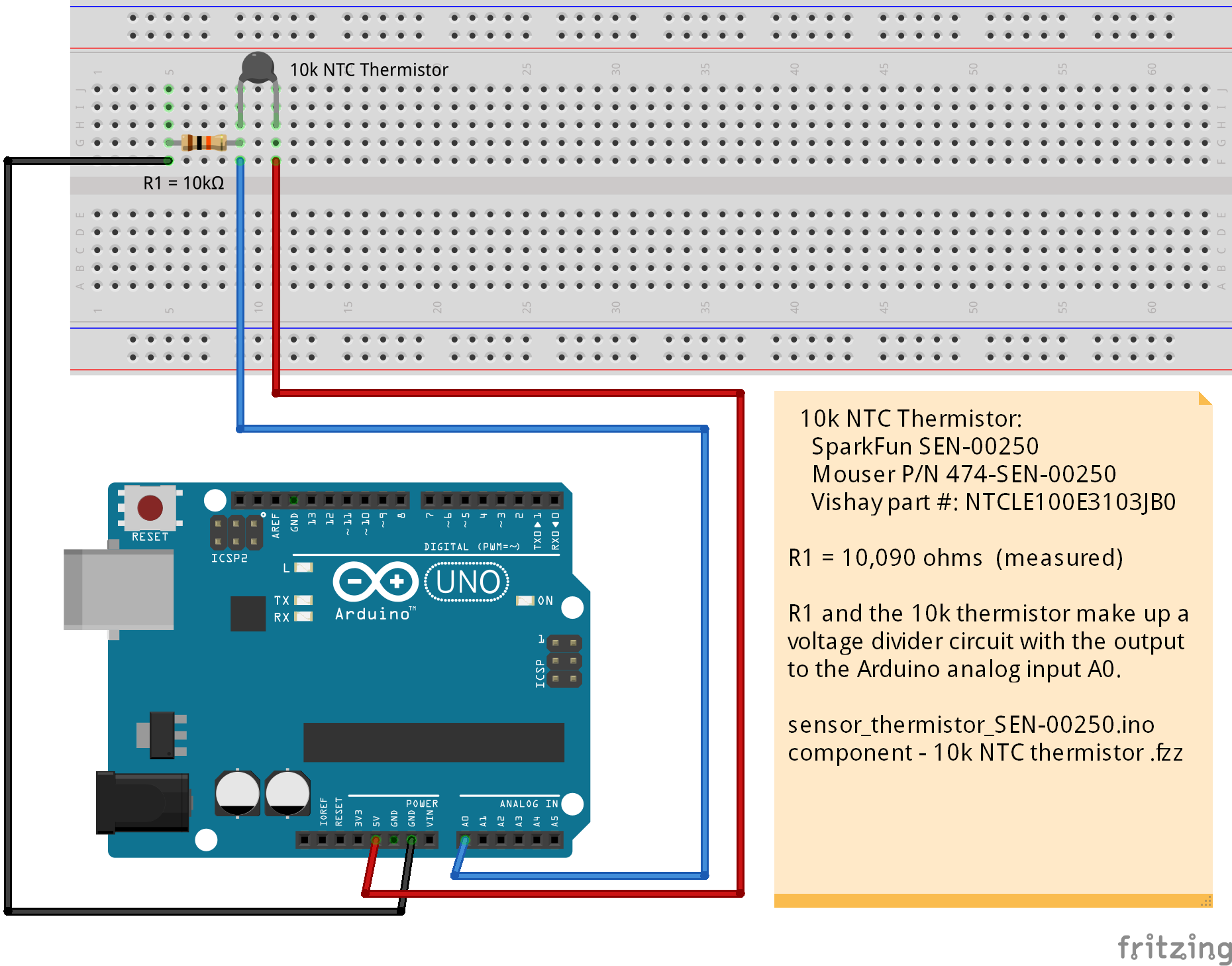
Below is a basic thermistor circuit based on a voltage divider. The size of the resistor in series with the thermisor should be the same (e.g. for a 10 k thermistor, use a 10 k ohm resistor).
Code
Get the constants for the Steinhart-Hart equation from your thermistor's datasheet if it is not the same as in this example and then update the code with the new values. The Steinhart-Hart equation is used to convert the sensor output to temperature. This code also allows you to put in the measured value for the 10 k resister in series with the thermistor (to make the voltage divider circuit), the voltage divider voltage input, and the microcontroller ADC full scale value. In this way, it may be adapted for any thermistor or microcontroller.
From the datasheet, identify the B25/85 value for your thermistor.
Then use the B25/85 value to lookup the A1,B1,C1,D1 constants for the Steinhart-Hart equation. Update GetThermisterTempF() in the code with those constant values.
/*

  Thermistor based temperature sensor.

  10k NTC Thermistor:
    SparkFun SEN-00250
    Mouser P/N 474-SEN-00250
    Vishay part #: NTCLE100E3103JB0

  Circuit:
    10.09 k resistor  (10,090 ohms)

*/

//////////////////////////////////////////////////////////////////////////////
// TimerA
// 10000000 us = 10000 ms = 10 sec = 0.1 Hz
// 1000000 us = 1000 ms = 1 sec = 1 Hz
// 100000 us = 100 ms = 0.1 sec = 10 Hz
// 10000 us = 10 ms = 0.01 sec = 100 Hz
// 1000 us = 1 ms = 0.001 sec = 1 kHz
// 100 us = 0.1 ms = 0.0001 sec = 10 kHz
const unsigned long timerA = 2000;
unsigned long timerAlap = millis();  // timer
/////////////////////////////////////////////////////////////////////////
const byte pinBuiltInLED = 13;
/////////////////////////////////////////////////////////////////////////
// Global variables for blinkLEDnoDelay()
unsigned long LEDblinkPeriod = 8;
unsigned long LEDblinkLast = 0;
byte LEDblinkPWM = 0;
bool LEDblinkState = false;
byte LEDlastMode = 0;
void blinkLEDnoDelay(byte pin, byte mode);
/////////////////////////////////////////////////////////////////////////
// 10k NTC Thermistor  NTCLE100E3103JB0
byte pinThermister = A0;
float R1 = 10090.0;   // 10,090 ohm resister in Thermister voltage divider circuit.


void setup () {
  pinMode(pinBuiltInLED, OUTPUT);
  delay(1);
  pinMode(pinThermister, INPUT);
  delay(1);

  //  DEFAULT: analog reference of 5 volts on 5V Arduino boards
  analogReference(DEFAULT);
  delay(1);

  Serial.begin(9600);
  while (!Serial) {
    digitalWrite(pinBuiltInLED, HIGH);
    delay(1);
    digitalWrite(pinBuiltInLED, LOW);
  }
  Serial.println("\nSerial ready");

  timerAlap = millis(); // reset the timer
} // setup()


void loop() {

  //  Timer A
  if (timerAlap > millis())  timerAlap = millis();
  if (millis() - timerAlap > timerA) {
    digitalWrite(pinBuiltInLED, HIGH);
    // Take a reading
    float dTempF = GetThermisterTempF(pinThermister);
    Serial.print("Temperature: ");
    Serial.print(dTempF);
    Serial.println(" F");
    digitalWrite(pinBuiltInLED, LOW);
    timerAlap = millis(); // reset the timer
  }

} // loop()


////////////////////////////////////////////////////////////////


float GetThermisterTempF(byte pinADC) {
  // Read the 10k NTC Thermistor and return the temperature in F.

  //  10k NTC Thermistor:
  //    SparkFun SEN-00250
  //    Mouser P/N 474-SEN-00250
  //    Vishay part #: NTCLE100E3103JB0

  int iADC = analogRead(pinADC);

  // ADC constants below used for ADC conversion to mV
  // 10 bit, 0 to 1023, or 1024 steps  (Arduino)
  // 12 bit, 0 to 4095, or 4096 steps
  const float FSadc = 1024.0;

  // FSmV is the full scale value in mV for the analog input at pinADC.
  // (it is NOT the voltage input to the voltage divider).
  // Use 5000.0 mV for 5 V (Arduino), use 3300 mV for 3.3 V microcontrollers.
  const float FSmV = 5000.0;

  // Calculate the voltage measured at pin ADC.
  float mV = iADC*(FSmV/FSadc);

  // Calculate the circuit resistance from the measured mV (at pinADC)
  // using the voltage divider circuit formula:
  //   Vout = Vin * (R2 / (R1 + R2))
  //   R2 = R1 * (Vin/Vout - 1)
  // Assign to Vin the voltage going into the thermistor voltage divider
  // circuit. Typically this would be the same as FSmV.
  float Vin = 5000.0;
  float R2 = R1 * (Vin / mV - 1.0);

  // Convert resistance to temperature using Steinhart–Hart equation
  // a1,b1,c1,d1 and equation from Vishay datasheet
  float a1=3.354016E-3, b1=2.569850E-4, c1=2.620131E-6, d1=6.383091E-8;
  float Rref = 10000.0;   // This is a 10 k thermister
  float T = 1/(a1+b1*log(R2/Rref)+c1*log(R2/Rref)+d1*log(R2/Rref));
  // T is in degrees Kelvin
  T = T - 273.15; // degrees C
  T = (T * 9.0)/ 5.0 + 32.0;    // degrees F
  return T;
} // GetThermisterTempF()
Do you need help developing or customizing a IoT product for your needs? Send me an email requesting a free one hour phone / web share consultation.
The information presented on this website is for the author's use only. Use of this information by anyone other than the author is offered as guidelines and non-professional advice only. No liability is assumed by the author or this web site.
.png)
.png)




.png)


.png)




.png)
.png)


.png)


.png)

.png)
.jpg)

.png)


.png)

.jpg)


.png)
