Particle Hardware
Hardware Overview
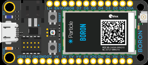
The Boron/Argon main processor is the Nordic Semiconductor nRF52840 SoC. It consists of a ARM Cortex-M4F 32-bit processor @ 64MHz, and has 1MB flash, 256KB RAM, ARM TrustZone CryptoCell-310 Cryptographic and security module low energy bluetooth (BLE), and a NFC-A radio. The Boron LTE has a LTE Cat M1 module for cellular communications. The Argon's Wi-Fi is an ESP32 with 801.11 b/g/n support.
Usefull Direct Links
- Particle Apps (online IDE)
- Particle Console
- Hardware pin reference table diagram
- Particle WorkBench (Visual Studio Code) tutorial
- Documentation
Hardware
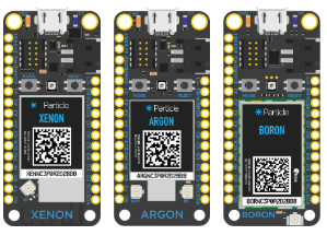
Put your Xenon/Agron/Boron into DFU mode
The DFU mode is identified by the LED on the Xenon blinking yellow. Put the Xenon into DFU mode by holding down the MODE button, then press the RESET button briefly while continuing to hold the MODE button until the LED begins blinking yellow. The LED will blink magenta (red & blue) at first, then only yellow.
particle usb dfu
Put your Xenon/Agron/Boron into Listening mode
Pinout Diagram
The pinout diagram below is organized to lay over the physical footprint of the devices when they are oriented with the USB connector at the top, and looking from the top of the devices (header pins pointing downward).
| Boron Argon Xenon |
Feather Spec. |
| | Boron Argon Xenon |
Feather Spec. |
|---|---|---|---|---|
| RST | RST | | | --- | --- |
| 3V3 | 3V3 | | | --- | --- |
| D20 | ARf | | | --- | --- |
| GND | GND | | | --- | --- |
| A0 D19 | A0 | | | Li+ | Li+ |
| A1 D18 | A1 | | | EN | EN |
| A2 D17 | A2 | | | Vusb | Vusb |
| A3 D16 | A3 | | | D8 UART2 RTS |
D13 |
| A4 D15 | A4 or D24 (2) | | | D7 LED |
D12 |
| A5 D14 SS | A5 or D25 (2) | | | D6 UART2 CTS |
D11 |
| D13 SCK |
SCK | | | D5 UART2 RX |
D10 |
| D12 MOSI |
MOSI | | | D4 UART2 TX MISO |
D9 |
| D11 MISO |
MISO | | | D3 SCL1 MOSI UART1_CTS |
D6 |
| D10 UART1 Tx |
Rx | | | D2 SDA1 SCK UART1_RTS |
D5 |
| D9 UART1 Rx |
Tx | | | D1 SCL |
SCL |
| NC | (1) | | | D0 SDA |
SDA |
Color Key: SPI SPI1 I2C
(1) free pin that varies in use
2(2 D24 and D25 can be used in place of A4 and A5 when the pins to not feature any analog capabilities.
The battery pin is on pin #24 or "BATT". The charge LED is on pin #26 or "CHG".
Feather pins in the IDE are referenced as "A0" or "14". Digital output should be limited to 7 mA per pin, so use a 680 ohm or higher resistor with an LED. Max 130 mA for total package.
Argon / Boron pins in the IDE are referenced as "A0" or "D14". Digital output should be limited to 9 mA per pin. Digital input HIGH when > 2.31 V, LOW < 0.99 V. Pull-up / pull-down resistance 13 kΩ.
LED built-in LED
3V3 is the primary power from Feathers to Wings. Regulator output is 1000 mA minus the Boron LTE (490 mA) and Argon (240 mA peak).
RST pulled low to reset the Feather.
Vusb power input to device. Should be 4.5 to 5.5V @ 500 mA
VBAT is power from the optional LiPoly battery. 3.0 to 3.7 V
EN pin enables the switch/regulator. The EN pin is pulled to ground during shutdown. The EN pin is connected to SYS_PWR_EN which is pulled high via a 100k resistor (~ 3.8V). The Boron will charge the LiPo while the EN pin is pulled low (shutdown), HOWEVER - if the charge current is applied while the Boron is shutdown (i.e. prior to shutdown it was not charging), then it will NOT charge.
Feather & FeatherWing Overview
Input power to the Argon / Boron/ Xenon
USB port The USB port with at least 500 mA supply is the primary power connection. The USB port input power is regulated down to 3.3 VDC by the Argon / Boron / Xenon and is available on pin '3V3'. It also charges any connected 3.7 V LiPoly battery (LiPo battery output is 4.2 V fully charged).
Vusb You may provide at least 500 mA @ 4.5 to 5.0 VDC directly to the Vusb pin, rather than using the USB port (don't use both!). When Vusb is is supplied power, it will provide power to the device, and charge any connected LiPo battery.
3V3 pin You can provide at least 500 mA @ 3.3 VDC directly to the '3V3' pin (max 3.6 V), provided you disable the XC9258A on board regulator by connecting the 'EN' pin #25 to ground, and then never connect power to the USB port or the LiPo connector. When you disable the on board regulator (EN to gnd), the output drops to about ~0.8 V (not 0).
Li+ pin You may provide at least 500 mA @ 3.6 to 4.2 VDC directly to the Li+ pin, rather than using the LiPo connector. This will charge the LiPo battery and provide power to the Argon / Boron / Xenon. Do not disable the on board regulator XC9258A).
Argon / Boron / Xenon Power Requirements
| Device | Max [mA] | Min [mA] | |
|---|---|---|---|
| Xenon | 32 mW | ||
| Boron LTE | 70 mW | 120 to 480 | |
| Argon | 150+ mW |
The Gen 3 (Argon, Boron, Xenon) devices have 4096 bytes of emulated EEPROM.
Low Energy Bluetooth
Bluetooth LE (BLE)5 is built into the Nordic Semiconductor nRF52840 SoC main processor. Code written for the nRF51 will not work on the nRF52.
Do you need help developing or customizing a IoT product for your needs? Send me an email requesting a free one hour phone / web share consultation.
The information presented on this website is for the author's use only. Use of this information by anyone other than the author is offered as guidelines and non-professional advice only. No liability is assumed by the author or this web site.
.jpg)

 (4).png)


.png)




.jpg)
.png)
.png)