June 2018
Feather Transmission Pressure Monitor
.png)
The bezel was 3D printed by Marando Industries Inc
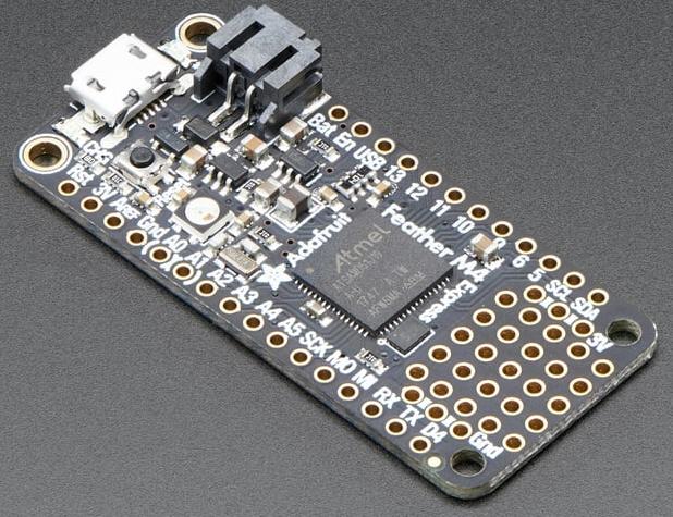
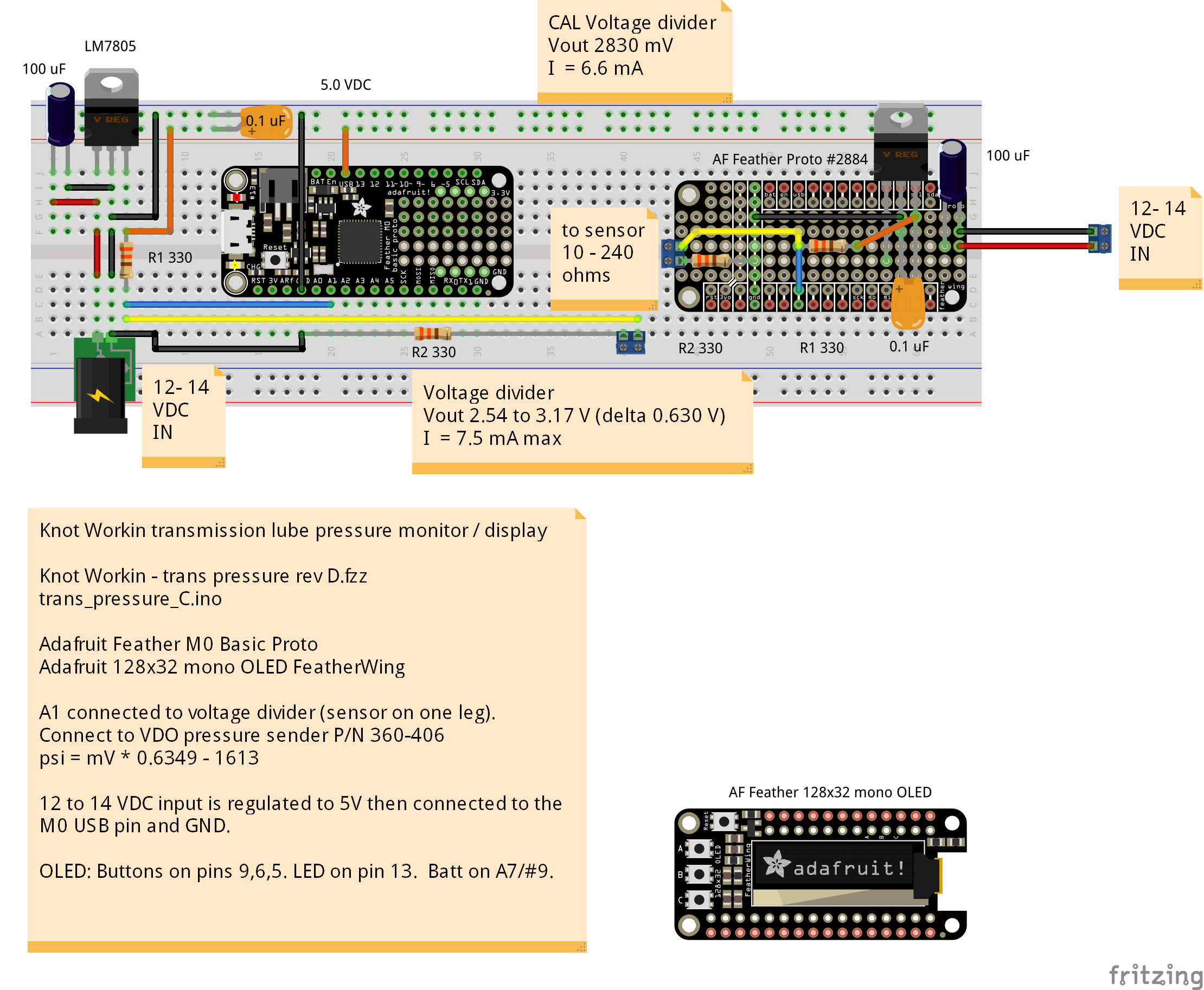
The 330 Hp Cummins engine in the boat my (named "Knot Workin") mates to a ZF transmission. I wanted to monitor the transmission lubrication pressure, so I installed a VDO pressure sender P/N 360-406. The pressure sender has an output of 10 to 240 ohms. The problem is, most standard pressure gauges for marine applications (or other) don't expect to see pressures as high as 435 psi. So I made my own pressure display using the Adafruit Feather M0 Basic Proto and a Adafruit 128x32 mono OLED FeatherWing (shown in the image above) to display the pressure. I used the Feather, because I didn't have a lot of room on my console for the display.
The pressure sensor has a 330 ohm resistor between it and ground, and the other leg goes to a voltage divider. Analog input pinADC sees a voltage divider with R1 = 330 ohms, R2 = 330 + sensor (10 to 240 ohms), or a range of 2540 mv @ 0 psi, to 3170 mV at 400 psi. psi = mV * 0.6349 - 1613.
Pressure sensor measured values were 62 ohms at idle (out of gear), and 200 ohms in gear. The owner's manual states that at the pump pressure take off (where the sensor is mounted), the normal range is 4 bar (58 psi) to 30 bar (435 psi). I created two shunt cal resistors: 100 ohm = 2830 mV = 184 psi, and 220 ohm = 3130 mV = 374 psi to test the display.
Button A on the display turn the OLED on/off (for night sailing) Button B on the display switches between the display of mV and psi.
/*

Knot Workin transmission lube pressure monitor / display

See:  Knot Workin -trans pressure revD.fzz for circuit

Display the transmission lube pressure measured at pinADC on
the OLED.  The presssure sender is VDO P/N 360-406 with
an output of 10 to 240 ohms.  The pressure sensor has a
330 ohm resistor between it and ground, and the other leg
goes to a voltage divider.  Analog input pinADC sees a voltage
divider with R1 = 330 ohms, R2 = 330 + sensor (10 to 240 ohms),
or a range of 2540 mv @ 0 psi, to 3170 mV at 400 psi.
psi = mV * 0.6349 - 1613.

Pressure sensor measured values were 62 ohms at idle (out of gear),
and 200 ohms in gear.
The owner's manual states at the pum pressure take off (where the
sensor is mounted), the normal range is 4 bar (58 psi) to
30 bar (435 psi).

Shunt cal resistors:
100 ohm = 2830 mV = 184 psi
220 ohm = 3130 mV = 374 psi


The power input is 12 to 14.3 VDC and is regulated to
a 5.0V by a LM7805.

BUTTON_A toggles the OLED ON/OFF (sw);
BUTTON_B toggles psi / mV;

Connections:
  A2 = pressure sensor (through voltage divider)
  5.0 VDC to VBUS (USB1)
  GND to 12 VDC ground
  The LiPoly is not intended to be used for this application.


Adafruit Feather M0 Basic Proto - ATSAMD21 Cortex M0
https://learn.adafruit.com/adafruit-feather-m0-basic-proto?view=all


Adafruit 128x32 mono OLED FeatherWing
https://www.adafruit.com/product/2900
28x32 monochrome OLED + three user buttons.
Display area: ~25.8mm / ~1.0"
The OLED I2C address is 0x3C and cannot be changed
https://learn.adafruit.com/adafruit-oled-featherwing?view=all
https://learn.adafruit.com/adafruit-gfx-graphics-library?view=all
http://henrysbench.capnfatz.com/henrys-bench/arduino-adafruit-gfx-library-user-guide/
http://engineeringnotes.blogspot.com/2013/07/using-ssd1306-textgraphics-display.html


*/

//////////////////////////////////////////////////////////////////////////////
//  Adafruit 128x32 mono OLED FeatherWing
//  Adafruit Feather M0 Basic Proto - ATSAMD21 Cortex M0

#include "SPI.h"
#include "Wire.h"
#include "Adafruit_GFX.h"
#include "Adafruit_SSD1306.h"

Adafruit_SSD1306 display = Adafruit_SSD1306();
// Configure the buttons, LED, batt pins, based on the microcontroller core
#if defined(ESP8266)
  #define BUTTON_A 0
  #define BUTTON_B 16
  #define BUTTON_C 2
  #define LED      0
  //#define VBATPIN ??  //3.7V Lithium polymer battery monitoring
#elif defined(ESP32)
  #define BUTTON_A 15
  #define BUTTON_B 32
  #define BUTTON_C 14
  #define LED      13
  //#define VBATPIN ??  //3.7V Lithium polymer battery monitoring
#elif defined(ARDUINO_STM32F2_FEATHER)
  #define BUTTON_A PA15
  #define BUTTON_B PC7
  #define BUTTON_C PC5
  #define LED PB5
  //#define VBATPIN ??  //3.7V Lithium polymer battery monitoring
#elif defined(TEENSYDUINO)
  #define BUTTON_A 4
  #define BUTTON_B 3
  #define BUTTON_C 8
  #define LED 13
  //#define VBATPIN ??  //3.7V Lithium polymer battery monitoring
#elif defined(ARDUINO_FEATHER52)
  #define BUTTON_A 31
  #define BUTTON_B 30
  #define BUTTON_C 27
  #define LED      17
  //#define VBATPIN ??  //3.7V Lithium polymer battery monitoring
#elif  __AVR_ATmega32U4__
  // 32u4
  #define BUTTON_A 9
  #define BUTTON_B 6
  #define BUTTON_C 5
  #define LED      13
  //#define VBATPIN ??  //3.7V Lithium polymer battery monitoring
#elif defined(_VARIANT_ARDUINO_ZERO_)
  // Feather M0 / Arduino Zero
  #define BUTTON_A 9
  #define BUTTON_B 6
  #define BUTTON_C 5
  #define LED      13
  #define VBATPIN A7  //3.7V Lithium polymer battery monitoring
#else // M4, and 328p
  // Note that #9 for BUTTON_A is also used for the battery
  // voltage divider, so if you want to use them both, make
  // sure to disable the pullup when you analog read, then
  // turn on the pullup for button reads.
  #define BUTTON_A 9
  #define BUTTON_B 6
  #define BUTTON_C 5
  #define LED      13
  #define VBATPIN A6  //3.7V Lithium polymer battery monitoring
#endif

#if (SSD1306_LCDHEIGHT != 32)
 #error("Height incorrect, please fix Adafruit_SSD1306.h!");
#endif

//////////////////////////////////////////////////////////////////////////////

// Show serial messages when DEBUG = true, otherwise minimize them.
#define DEBUG false

//////////////////////////////////////////////////////////////////////////////
//  ADC constants
// Constants below used to convert raw ADC values to mV.
// 10 bit, 0 to 1023, or 1024 steps
// 12 bit, 0 to 4095, or 4096 steps
const float FSadc = 1024.0;
// FSmV = 3300 for 3.3 V microcontrollers, 5000 for 5.0 V microcontrollers.
const float FSmV = 3300.0;
//////////////////////////////////////////////////////////////////////////////
//  Analog input
byte pinADC = A1;
// dAdj_mV is multiplied by the reading at pinADC in mV to get the input voltage to a
// voltage divider or other component.
const float dAdj_mV = 1.0;
// 3.3 V full scale (3300 mV); 0 to 1023 steps (1024 total steps) for 10 bit
// 187 ADC reading * (3300/1024) = 600 mV
int iSamples = 0;
const int iMaxSamples = 100;
float dCumAvg = 0.0;
float dLastAvg = 0.0;
//////////////////////////////////////////////////////////////////////////////
boolean bShowPsi = true;
boolean bOLEDon = true;

void setup() {
  #if DEBUG
    Serial.begin(9600);
    while (!Serial) {
      delay(1);
    }
    Serial.println("Serial ready");
  #endif

  // Adafruit 128x32 mono OLED FeatherWing
  // by default, generate the high voltage from the 3.3v line internally.
  // initialize with the I2C addr 0x3C (for the 128x32)
  delay(100);  // Give the OLED driver time to bring it's internal charge up to voltage.
  display.begin(SSD1306_SWITCHCAPVCC, 0x3C);
  // init done
  #if DEBUG
    Serial.println("OLED begun");
  #endif

  // Show image buffer on the display hardware.
  // Since the buffer is intialized with an Adafruit splashscreen
  // internally, this will display the splashscreen.
  // The image buffer on the display hardware is initialized
  // with an Adafruit splashscreen.  If you execute the command
  // display.display(), then the splashscreen will be shown.
  // Disable this command if you don't want to display the
  // splashscreen.
  //display.display();
  //delay(1000);

  // Configure the three buttons on the OLED FeatherWing
  pinMode(BUTTON_A, INPUT_PULLUP);  // On BUTTON_A and used by battery monitor on pin_BATT
  delay(10);
  //pinMode(BUTTON_B, INPUT_PULLUP); // Button B has a 100k pullup on it from the OLED so it will work with the ESP8266.  Therefore do NOT set the internal pullup.
  delay(10);
  pinMode(BUTTON_C, INPUT_PULLUP);
  delay(10);

  display.clearDisplay();
  // Turn off text wrapping
  display.setTextWrap(false);
  display.setTextColor(WHITE);
  //  .setTextSize(2) will change the character sizes as follows:
  //    2*6 x 2*8 = 12x16 pixels.
  //  For a 128x32 OLED, 128/12 = 10 chars wide; 32/16 = 2 characters tall
  display.setTextSize(1);
  display.setCursor(0,0);
  display.print("Button A  OLED ON/OFF");
  //display.print("012345678901234567890");
  display.setCursor(0,16);
  display.print("Button B  mV/psi");
  //display.print("012345678901234567890");
  display.display();
  delay(3000);

  blinkLED(LED);
  #if DEBUG
    Serial.println("Setup complete");
  #endif
} // setup()


void loop() {
  CheckADC();
  if (digitalRead(BUTTON_A) != HIGH) {
    // toggle display ON/OFF
    display.clearDisplay();
    display.setTextSize(2);
    if (bOLEDon == true) {
      bOLEDon = false;
      display.setCursor(0,0);
      display.print("OLED OFF");
      #if DEBUG
        Serial.println("OLED OFF");
      #endif
    } else {
      bOLEDon = true;
      display.setCursor(0,0);
      display.print("OLED ON");
      #if DEBUG
        Serial.println("OLED ON");
      #endif
    }
    display.display();
    delay(2000);
  }//BUTTON_A
  if (digitalRead(BUTTON_B) != HIGH) {
    // toggle display of psi & mV
    display.clearDisplay();
    display.setTextSize(2);
    if (bShowPsi == true) {
      bShowPsi = false;
      display.setCursor(0,0);
      display.print("display mV");
      //display.print("0123456789");
      #if DEBUG
        Serial.println("mV");
      #endif
    } else {
      bShowPsi = true;
      display.setCursor(0,0);
      display.print("display psi");
      #if DEBUG
        Serial.println("PSI");
      #endif
    }
    display.display();
    delay(2000);
  }//BUTTON_B
  if (digitalRead(BUTTON_C) != HIGH) {
  }//BUTTON_C
  // The yield() function allows ESP8266 microcontroller to run a
  // number of utility functions in the background, without causing
  // the ESP8266 to crash or reset. Include it within any
  // while() + digitalRead() and other loops;
  yield();
} // loop()


void CheckADC() {
  // Output the average pinADC value whenever it changes (only).
  // (The comparison is integer based from the mV value)
  // Flash the LED whenever iMaxSamples have been read.
  if (iSamples < iMaxSamples) {
    iSamples += 1;
    dCumAvg += Get_mVfromADC(pinADC, dAdj_mV);
    digitalWrite(LED, LOW);
  } else {
    float mV = dCumAvg / iSamples;
    iSamples = 0;
    dCumAvg = 0.0;
    digitalWrite(LED, HIGH);
    printADCmV(pinADC, mV);
    dLastAvg = mV;
  }
}  //CheckADC()

float Get_mVfromADC(byte pinADC, float mVadj) {
  // Read the value from the sensor and convert ADC to mV.
  // The input to pinADC in mV is multipled by mVadj to
  // correct for any voltage divider or other component.
  // Global variables FSmV and FSadc convert the raw ADC
  // values to the mV measured at pinADC.
  int ADCval = analogRead(pinADC);  // discard the 1st value
  delay(10);
  ADCval = analogRead(pinADC);
  delay(10);
  float mV = ADCval*(FSmV/FSadc);
  mV *= mVadj;
  return mV;
}  // Get_mVfromADC()


void printADCmV(byte pinADC, float mV) {
  #if DEBUG
    Serial.print("A (");
    Serial.print(pinADC);
    Serial.print(") = ");
    Serial.print((int)mV);
    Serial.println(" mV");
  #endif
  if (bOLEDon == true) {
    // print to OLED
    display.clearDisplay();
    display.setTextSize(1);
    display.setCursor(0,0);
    display.print("Transmission Pressure");
    //display.print("012345678901234567890");
    display.setTextSize(2);
    //display.print("0123456789");
    display.setCursor(0,16);
    if (bShowPsi == true) {
      float dPsi = mVtoPSI(mV);
      int iPsi = int(dPsi);
      display.print(iPsi);
      display.print(" psi");
    } else {
      display.print((int)mV);
      display.print(" mV");
    }
    display.display();
  } else {
    display.clearDisplay();
    display.display();
  }
} //printADCmVDC ()

float mVtoPSI(float mV) {
  // Voltage divider consisting of R1 = 330 ohm resistor
  // and the sensor with an output of 10 to 240 ohms
  // going into the R2 leg of the voltage divider with
  // another 330 ohm resistor in series (R2 total = 340 to 57 ohms).
  // Vin = 5 VDC.  Max current 7.5 mA.
  // mV = (Vin*R2)/(R2+R1)
  // mV = (5.0 * (sensor + 330) / ((sensor + 330) + R1)
  // Sensor @ 0 psi = 10 + 330 = 340 ohms = 2540 mV
  // Sensor @ 400 psi = 240 + 330 = 570 ohms = 3170 mV
  // For mV = 2830 mV (100 ohm resister shunt cal), 184 psi.
  float dPSI = 0.6349 * mV - 1613.0;
  //if ((int)dPSI < 1) dPSI = 0.0;
  dPSI = fabs(dPSI);
  return dPSI;
}

void blinkLED(byte ledPIN){
  //  consumes 300 ms.
  for(int i = 5; i>0; i--){
    digitalWrite(ledPIN, HIGH);
    delay(30);
    digitalWrite(ledPIN, LOW);
    delay(30);
  }
}//blinkLED()
Do you need help developing or customizing a IoT product for your needs? Send me an email requesting a free one hour phone / web share consultation.
The information presented on this website is for the author's use only. Use of this information by anyone other than the author is offered as guidelines and non-professional advice only. No liability is assumed by the author or this web site.
.png)




.png)
