November 2022
Feather RV Monitor
Functional Requirements
- Trigger dog barking sound inside RV when the motion of a human or animal is detected (I want to deter human visitors during the day, and be alerted of human/animal visitors at night).
- Motion sense monitor several points around the perimeter of the RV.
- All devices 12 VDC powered
- The unit that will reside inside the RV should have an 3.5 mm audio out jack for connection to powered speakers, a test pushbutton that will simulate the motion sensor trigger, a power on/off switch, an LED to confirm power is on, and an LED to indicate when the motion sensor trigger (or test pushbutton) has been triggered. Wireless communication between the unit inside the RV and the remote outside PIR sensors.
Implementation Overview
LoRa will be used for wireless communication between the PIR sensors and the device inside the RV. 12 VDC power will be routed to each PIR sensor + LoRa Feather mounted to the perimeter of the RV. PIR motion sensors that are available will be assessed to find the one with the best performance.
Hardware
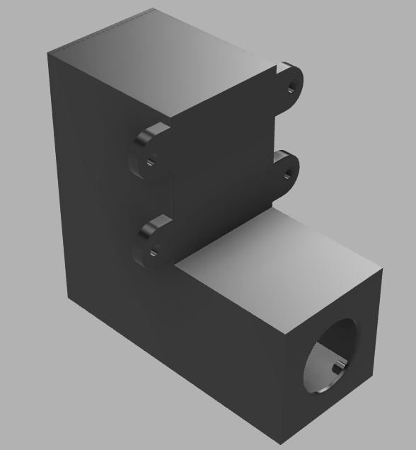
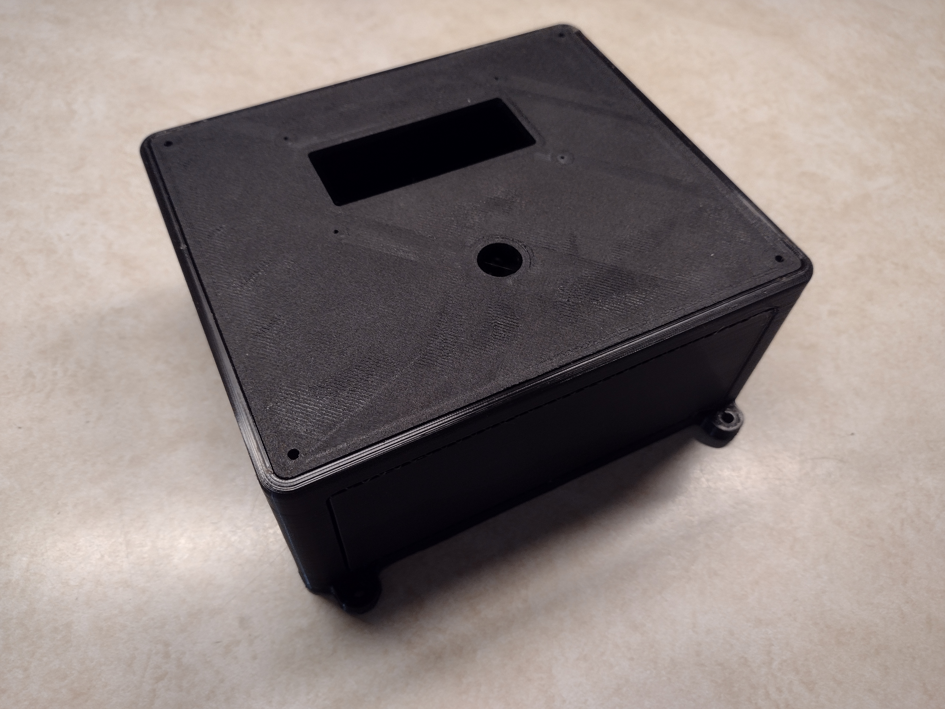
Custom Enclosures
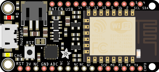
PIR Sensor + LoRa Feather
Sound + LoRa
Receiving Unit Inside RV
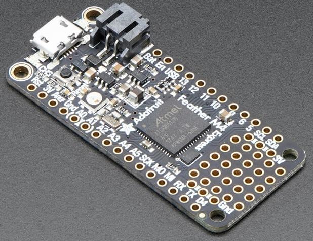
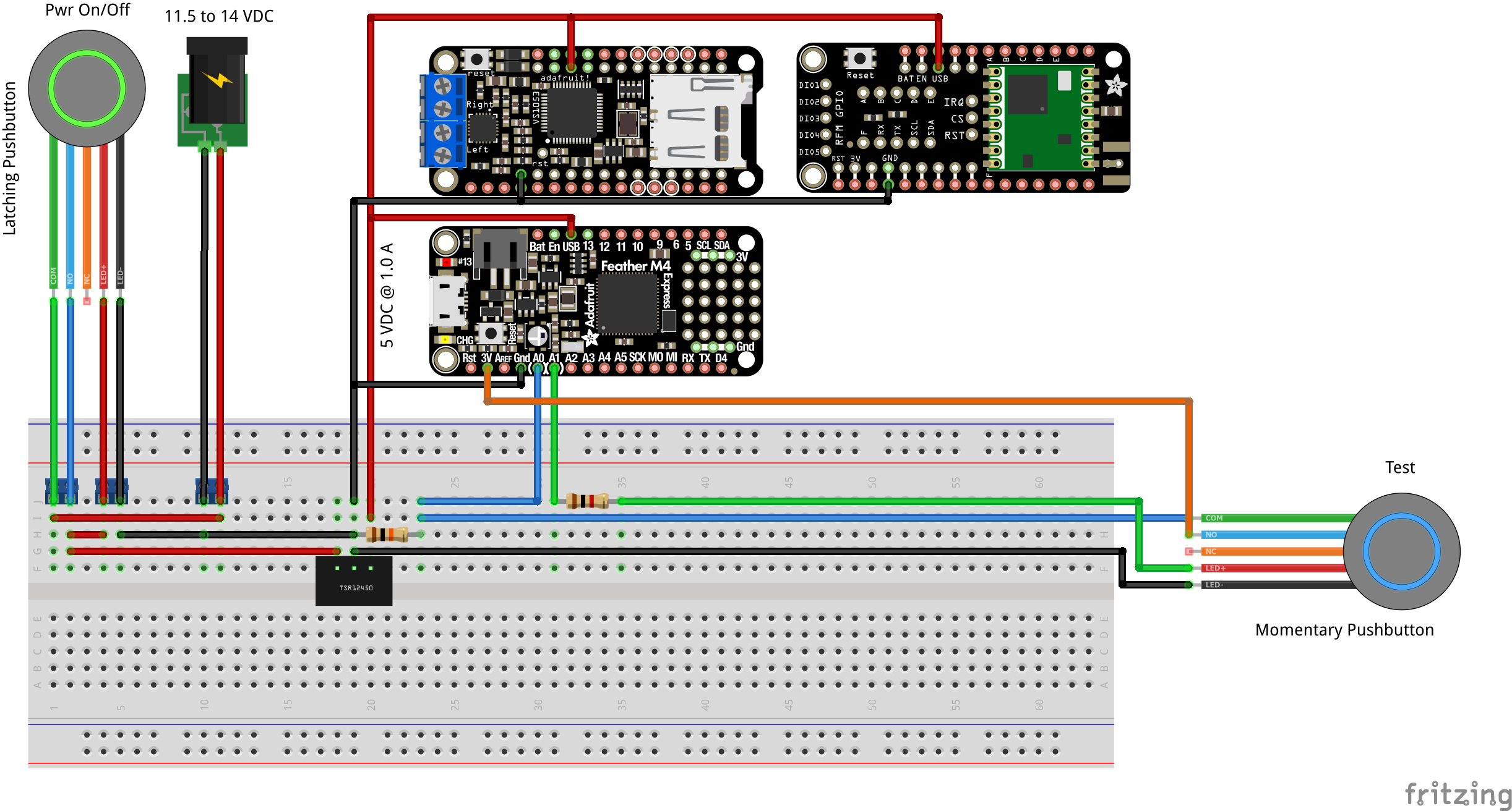
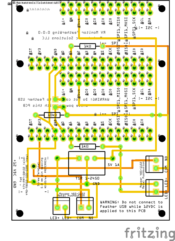
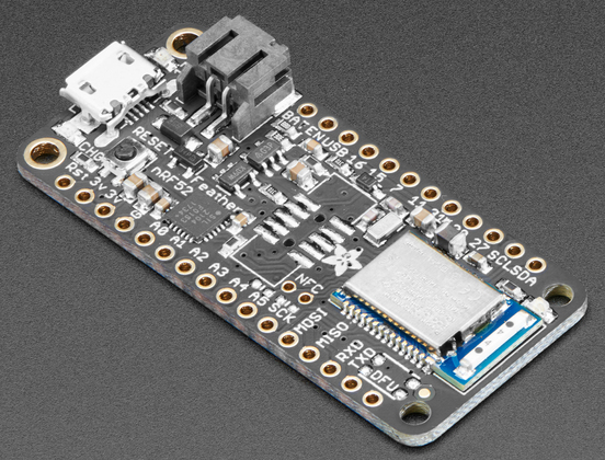
Adafruit M4 Express ATSAMD51 Cortex M4 with a Adafruit FeatherWing Music Maker and a LoRa FeatherWingstacked on top. A latching pushbutton with LED will turn on/off 12 VDC power to the device, and indicate that power is on via the built-in pushbutton LED. A custom PCB will provide power to the M4 Express + Music Maker via the Vbus connection, and connections for:
- Play Signal - the digital input will go HIGH to signal the Music Maker to play the designated audio files.
- Test btn - a pushbutton mounted on the enclosure and connected to the Play Signal, will allow the user to manually trigger the Play Signal.
- Ext LED - an external LED mounted to the enclosure will indicate power on, and when the Play Signal or Test btn have triggered audio playback.
- A momentary pushbutton with built-in LED solves the requirements for 'Test btn' and 'Ext LED'.
The FeatherWing Music Maker and LoRa FeatherWing for the receiving unit that will be located in the RV consume a lot of pins. With careful assignment of pins for the LoRa, I was able to allocate the pins required from the M4 Express ATSAMD51 Cortex M4 as shown in the table below.
| Custom PCB |
Feather Music Maker |
Feather M4 Express |
LoRa | | | Custom PCB |
Feather Music Maker |
Feather M4 Express |
LoRa |
|---|---|---|---|---|---|---|---|---|
| RST | RST | RST | | | --- | --- | |||
| 3V3 | 3V3 | | | --- | --- | ||||
| ARf | | | --- | ||||||
| GND | GND | GND | | | --- | --- | |||
| Play Signal |
A0 D14 | | | Vbat | |||||
| Ext LED | A1 D15 | | | EN | |||||
| A2 D16 | CS | | | 5V PS | Vbus | ||||
| A3 D17 | RST | | | D13 LED |
|||||
| A4 D18 | IRQ | | | ||||||
| | | ||||||||
| SCK | D25 SCK |
SCK | | | XDCS | D10 | |||
| MOSI | D24 MOSI |
MOSI | | | DREQ | D9 | |||
| MISO | 23 MISO |
MISO | | | MP3CS | D6 | |||
| | | SD CS | D5 | ||||||
| D1 | MIDI RX | | | D21 SCL |
|||||
| | | D22 SDA |
Color Key: SPI I2C (I2C pullup on FeatherWing, not Feather)
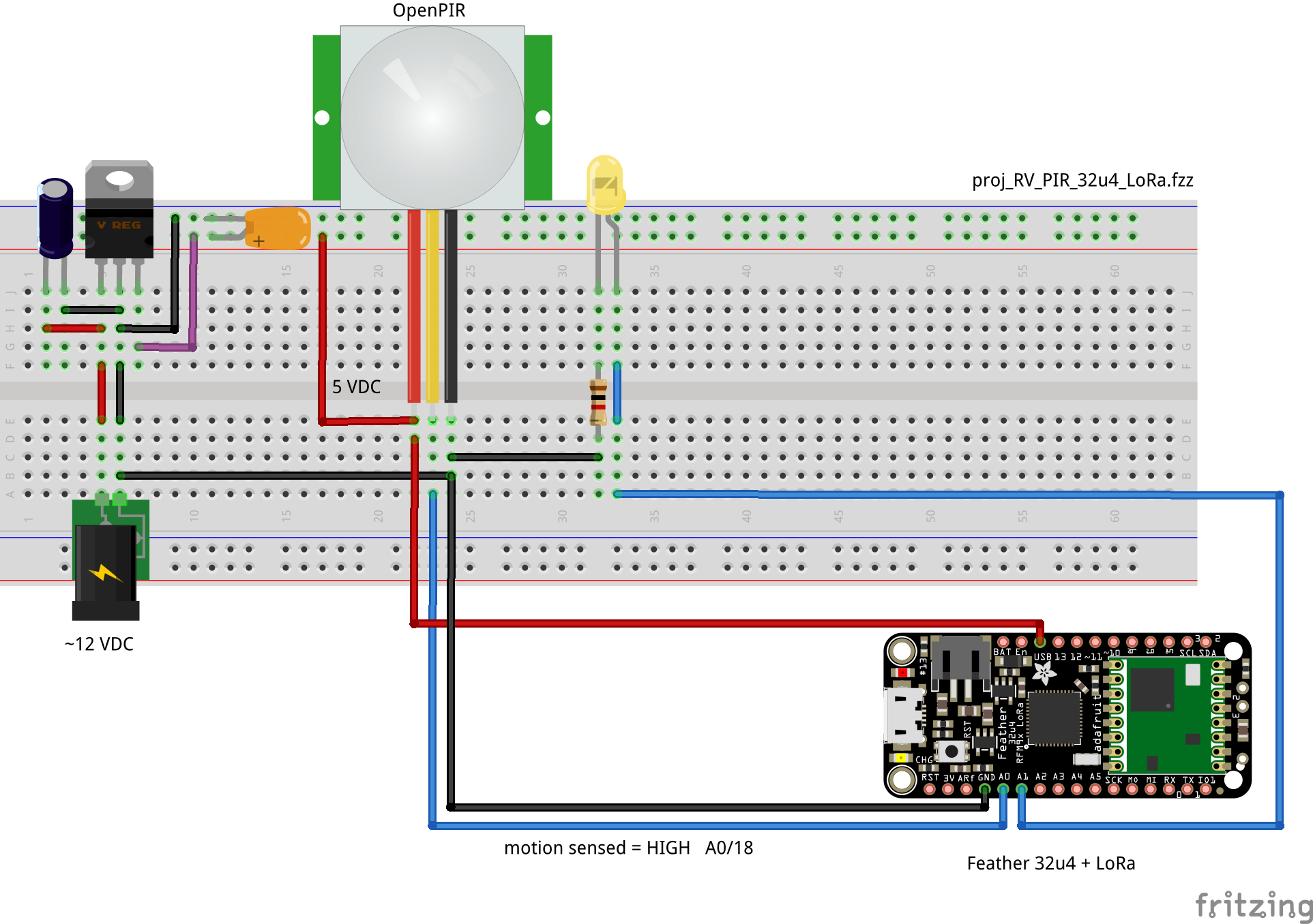
Breadboard Schematic
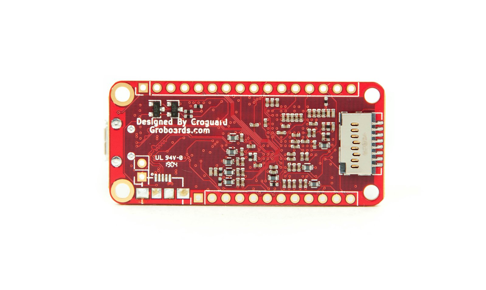
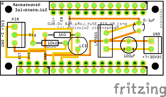
PCB
Sending Unit With PIR on Outside of RV
A OpenPIR sensor is connected to an integrated Feather 32u4 with LoRa to sense mammal motion and transmit a message to the receiving LoRa device inside the RV.
Firmware
The LoRa software chosen was the RadioHead Reliable Datagram library. The "Reliable Datagram" mode is reliable in the sense that messages are acknowledged by the recipient, and unacknowledged messages are retransmitted until acknowledged or the retries are exhausted. However, my testing found that rarely a transmission would not be acknowledged, and ocassionally the acknowledgement by the receiving unit would not occur.
I wanted to treat the PIR digital output as an event that I didn't want to miss, rather than as a sensor value to be repeated. So I built into the code persistant transmission of the message, and persistant acknowledgement (with a timeout). I also made sure communication between the Tx and Rx device was possible by sending a communication confirmation message between the two if none had occurred for at least 55 seconds. If no message is received by the receiving unit for 60 seconds, then a visual indication is shown on the Rx device.
The Rx unit will ignore messages from any other unit other than one with an address expected. The LoR message consists of an unencrypted byte array of size 16. This was chosen so that although I send simple small integers (0 to 255) between the Tx and Rx device, I could have encrypted those messages, and sent floating point sensor values. This allows the code to be easily adapted for other purposes.
Tx Device Firmware
/*

  Feather ATmega32u4 + LoRa
  Adafruit Product ID 3078

  Send message via LoRa reliable datagram, and if any fails, repeat Tx
  until the message is sent.
  The reliability of this sketch at 1 Hz is nearly 100%.

  ATmega32u4 chip running at 8 MHz
  Built-in LED on pin #13
  Battery voltage measurement on pin A9 (#9)
  Hardware UART is Serial1 on pins #0 and #1

  Built-in LED:
    Quick flash - LoRa Tx/Rx
    Constant on - Tx not acknowledged by other LoRa device.

*/

// In Arduino IDE install "Adafruit AVR Boards".
// In Arduino IDE, select 'Tools','Board','Adafruit Boards','Adafruit Feather 32u4'
// Find USB port in Windows by looking at ...

/////////////////////////////////////////////////////////////////////////
#define pinBuiltInLED 13
byte stateBuiltInLED = LOW;

// DEBUG turns on/off serial output
#define DEBUG false

void blinkERR(byte ledPIN){
  // S-O-S
  const int S = 150, O = 300;
  for(int i = 3; i>0; i--){
    digitalWrite(ledPIN, HIGH);
    delay(S);
    digitalWrite(ledPIN, LOW);
    delay(S);
  }
  delay(200);
  for(int i = 3; i>0; i--){
    digitalWrite(ledPIN, HIGH);
    delay(O);
    digitalWrite(ledPIN, LOW);
    delay(O);
  }
  delay(200);
  for(int i = 3; i>0; i--){
    digitalWrite(ledPIN, HIGH);
    delay(S);
    digitalWrite(ledPIN, LOW);
    delay(S);
  }
  delay(200);
} // blinkERR()

/////////////////////////////////////////////////////////////////////////

// Download the entire library from (look for .zip file link at top of page):
//  http://www.airspayce.com/mikem/arduino/RadioHead/index.html


// Feather 32u4 with LoRa (single device)
#include <SPI.h>
#include <RH_RF95.h>
#include <RHReliableDatagram.h>

#define SENDER_ADDRESS 1    // This device (primary Tx unit).
#define RECEIVER_ADDRESS 2  // The other LoRa device that receives messages.

#define RFM95_CS 8  //D8 or Arduino pin #2
#define RFM95_RST 4 //D4 or Arduin pin #25
#define RFM95_INT 7 //D7 or Arduino pin #1

#define RF95_FREQ 915.0
// Singleton instance of the radio driver
RH_RF95 rf95(RFM95_CS, RFM95_INT);

// Class to manage message delivery and receipt, using the rf95 declared above
RHReliableDatagram manager(rf95, SENDER_ADDRESS);

// Define data to be sent via LoRa
byte arrData[16]; // holds data to be sent via LoRa
byte buf[RH_RF95_MAX_MESSAGE_LEN]; // holds reply from receiver
unsigned long tx_count = 0;
bool tx_successful = true;

//////////////////////////////////////////////////////////////////////////////

#define pin_pir A0
unsigned long last_trigger = 0;
#define pin_ext_led  A1

byte last_pir_state = LOW;
unsigned long last_debounce = 0;  // the last time the output pin was toggled
unsigned long debounce_delay = 100;    // The switch debounce time.  50 to 100 ms
unsigned long last_pir_tx = 0;

//////////////////////////////////////////////////////////////////////////////
// TimerA
// 10000000 us = 10000 ms = 10 sec = 0.1 Hz
// 1000000 us = 1000 ms = 1 sec = 1 Hz
// 100000 us = 100 ms = 0.1 sec = 10 Hz
// 10000 us = 10 ms = 0.01 sec = 100 Hz
// 1000 us = 1 ms = 0.001 sec = 1 kHz
unsigned long timer_a_lap = millis();  // timer


void sendLoRaMsg(byte *arr, int len) {

    #if DEBUG
    Serial.print("arr: '");
    for (int i=0; i<len; i++) {
      Serial.print(char(arr[i]));
    }
    Serial.println("'");
    #endif

    tx_successful = false;
    tx_count++;
    unsigned long ack_count = 0;
    unsigned long ack_timer = millis();

    // Persistently send LoR message..
    do {
      ack_count++;
      // Method sendtoWait() will wait for an ack from the receipient.
      if (manager.sendtoWait(arr, len, RECEIVER_ADDRESS))   {
        // The receiver acknowledged the Tx
        tx_successful = true;
        digitalWrite(pinBuiltInLED, LOW);
        digitalWrite(pin_ext_led, LOW);
        #if DEBUG
        Serial.println("sendtoWait successful");
        #endif
      } else {
        #if DEBUG
        Serial.println("sendtoWait failed!");
        #endif
      } // manager.sendtoWait()
      #if DEBUG
      Serial.print("tx_count = "); Serial.print(tx_count);
      Serial.print("; ack_count = "); Serial.println(ack_count);
      Serial.println();
      #endif
    } while (tx_successful == false && millis() - ack_timer < 10000);
    delay(100);  // Give GPIO chance to settle down after LoRa Tx

    last_debounce = millis();
    timer_a_lap = millis(); // reset the timer
} // sendLoRaMsg()


void timerA() {
  // Send a LoRa message to the LoRa device every timer_interval_a
  // to confirm that LoRa communication is working.
  // The message is a random number between 0 and 254 (255 is PIR trigger).
  if (timer_a_lap > millis())  timer_a_lap = millis();
  if (millis() - timer_a_lap > 35000) {

    digitalWrite(pinBuiltInLED, HIGH);
    digitalWrite(pin_ext_led, HIGH);
    int n = random(0,254);
    for (int i=0; i<sizeof(arrData); i++) {
      arrData[i] = 0x20;  // space character
    }

    // ITOA() converts int to string
    // char* itoa(int num, char* buffer, int base)
    // The "(char*)" is a type cast that tells the compiler to treat arrData as a
    // char pointer and not as a bype array.  iota expect char* as the 2nd argument.
    itoa(n, (char*)arrData, 10);

    arrData[sizeof(arrData)-1] = 0x00;  // null character

    #if DEBUG
    Serial.println("timerA() triggered!");
    #endif
    sendLoRaMsg(arrData, sizeof(arrData));

    last_debounce = millis();
    timer_a_lap = millis(); // reset the timer
  }
} // timerA()


void sensorPIR() {
  // Must implement a debounce timer for managing the PIR sensor digital
  // output.
  byte pir_state = digitalRead(pin_pir);
  // if millis() or timer wraps around, reset it
  if (last_debounce > millis())  last_debounce = millis();
  if (last_pir_tx > millis()) last_pir_tx = millis();

  // Wait at least 15 seconds between each PIR Tx to give the
  // Music Maker time to play the last song.
  if (pir_state != last_pir_state && millis() - last_pir_tx > 15000) {
    // Multiple changes in the pir_state can occur when a pushbutton is
    // pressed, or a switch is toggled. Use a debounce timer to only react
    // to a change in button state after an interval of debounce_delay.
    last_pir_state = pir_state;
    //  Check if enough time has passed to evaluate another pushbutton press.
    if ((millis() - last_debounce) > debounce_delay) {
      if (pir_state == HIGH) {
          // PIR triggered!
          last_pir_tx = millis();
          digitalWrite(pinBuiltInLED, HIGH);
          digitalWrite(pin_ext_led, HIGH);

          // assign a space to arrData..
          for (int i=0; i<sizeof(arrData); i++) {
            arrData[i] = 0x20;  // space character
          }
          // ITOA() converts int to string
          // char* itoa(int num, char* buffer, int base)
          // The "(char*)" is a type cast that tells the compiler to treat arrData as a
          // char pointer and not as a bype array.  iota expect char* as the 2nd argument.
          itoa(255, (char*)arrData, 10);

          arrData[sizeof(arrData)-1] = 0x00;  // null character

          #if DEBUG
          Serial.println("sensorPIR() triggered!");
          #endif
          sendLoRaMsg(arrData, sizeof(arrData));

          timer_a_lap = millis(); // reset timerA
      } // pir_state
      last_debounce = millis();
    } // millis()
  } // pir_state != last_pir_state
} // sensorPIR()


/////////////////////////////////////////////////////////////////////////


void setup() {

  pinMode(pinBuiltInLED, OUTPUT);
  digitalWrite(pinBuiltInLED, LOW);

  pinMode(pin_ext_led, OUTPUT);
  digitalWrite(pin_ext_led, LOW);

  #if DEBUG
  Serial.begin(115200);
  while (!Serial) {
    delay(100);
    if (millis() % 2)
      digitalWrite(pinBuiltInLED, HIGH);
    else
      digitalWrite(pinBuiltInLED, LOW);
  }
  Serial.println("\nSerial ready");
  #endif
  digitalWrite(pinBuiltInLED, LOW);

  pinMode(pin_pir, INPUT);

  //////////////////////////////////////////////////////////////////////////////
  // LoRa

  pinMode(RFM95_RST, OUTPUT);
  digitalWrite(RFM95_RST, HIGH);

  // manual reset
  digitalWrite(RFM95_RST, LOW);
  delay(10);
  digitalWrite(RFM95_RST, HIGH);
  delay(10);

  while (!manager.init()) {
    #if DEBUG
    Serial.println("LoRa radio init failed");
    Serial.println("Uncomment '#define SERIAL_DEBUG' in RH_RF95.cpp for detailed debug info");
    #endif
    while (1) {
      blinkERR(pinBuiltInLED);
      blinkERR(pin_ext_led);
    }
  }
  Serial.println("LoRa radio init OK!");

  // Defaults after init are 434.0MHz, modulation GFSK_Rb250Fd250, +13dbM
  if (!rf95.setFrequency(RF95_FREQ)) {
    #if DEBUG
    Serial.println("setFrequency failed");
    #endif
    while (1) {
      blinkERR(pinBuiltInLED);
      blinkERR(pin_ext_led);
    }
  }
  #if DEBUG
  Serial.print("Set Freq to: "); Serial.println(RF95_FREQ);
  #endif

  // Defaults after init are 434.0MHz, 13dBm, Bw = 125 kHz, Cr = 4/5, Sf = 128chips/symbol, CRC on

  // The default transmitter power is 13dBm, using PA_BOOST.
  // If you are using RFM95/96/97/98 modules which uses the
  // PA_BOOST transmitter pin, then you can set the
  // transmitter powers from 5 to 23 dBm:
  rf95.setTxPower(23, false);

  //////////////////////////////////////////////////////////////////////////////

  randomSeed(millis());
  timer_a_lap = millis(); // reset the timer
  #if DEBUG
  Serial.println("setup finished\n");
  #endif
} // setup()


void loop() {

  timerA();

  sensorPIR();


} // loop()
Rx Device Firmware
/*

  Adafruit Feather M4 Express SAMD51
  Adafruit Music Maker FeatherWing
  LoRa FeatherWing (separate, stacked)

  In Arduino IDE, set board to 'Adafruit Feather M4 Express (SAMD51)'

  If bootloading frozen, click RST button twice quickly.

  The red LED will pulse and the RGB LED will be green when you are
  in bootloader mode.

  The yellow “charging” LED flickers constantly whenever the Feather is powered by USB

  Arduino C++ code or CircuitPython


  WARNING:  The Arduino IDE serial monitor causes setup() to wait until
  the serial monitor IDE is run.

*/


/////////////////////////////////////////////////////////////////////////
const byte pin_built_in_led = 13;

// DEBUG turns on/off serial output
#define DEBUG false

void blinkERR(byte ledPIN){
  // S-O-S
  const int S = 150, O = 300;
  for(int i = 3; i>0; i--){
    digitalWrite(ledPIN, HIGH);
    delay(S);
    digitalWrite(ledPIN, LOW);
    delay(S);
  }
  delay(200);
  for(int i = 3; i>0; i--){
    digitalWrite(ledPIN, HIGH);
    delay(O);
    digitalWrite(ledPIN, LOW);
    delay(O);
  }
  delay(200);
  for(int i = 3; i>0; i--){
    digitalWrite(ledPIN, HIGH);
    delay(S);
    digitalWrite(ledPIN, LOW);
    delay(S);
  }
  delay(200);
} // blinkERR()

/////////////////////////////////////////////////////////////////////////

// Download the entire library from (look for .zip file link at top of page):
//  http://www.airspayce.com/mikem/arduino/RadioHead/index.html


// Feather 32u4 with LoRa (single device)
#include <SPI.h>
#include <RH_RF95.h>
#include <RHReliableDatagram.h>

// LoRa FeatherWing with separate Feather M4 Express
#define RFM95_CS  16
#define RFM95_RST 17
#define RFM95_INT 18

#define RF95_FREQ 915.0
// Singleton instance of the radio driver
RH_RF95 rf95(RFM95_CS, RFM95_INT);

// The two addresses are an integer of type uint8_t (0 to 255 decimal).
#define SENDER_ADDRESS 1    // The LoRa device that sends messages to this device
#define RECEIVER_ADDRESS 2  // This LoRa device

// Class to manage message delivery and receipt, using the rf95 declared above
RHReliableDatagram manager(rf95, RECEIVER_ADDRESS);

byte buf[RH_RF95_MAX_MESSAGE_LEN];

/////////////////////////////////////////////////////////////////////////
//  Adafruit Music Maker FeatherWing

// Install the 'Adafruit_VS1053' & 'Adafruit_BusIO' libraries.
//  https://github.com/adafruit/Adafruit_VS1053_Library
//  https://github.com/adafruit/Adafruit_BusIO

// include SPI, MP3 and SD libraries
#include <SPI.h>
#include <SD.h>
#include <Adafruit_VS1053.h>

// These are the pins used
#define VS1053_RESET   -1     // VS1053 reset pin (not used!)

// Feather M4 Express (or ESP32S2, 328, m0, nrf52840, 32u4)
#define VS1053_CS       6     // VS1053 chip select pin (output)
#define VS1053_DCS     10     // VS1053 Data/command select pin (output)
#define CARDCS          5     // Card chip select pin
// DREQ should be an Int pin *if possible* (not possible on 32u4)
#define VS1053_DREQ     9     // VS1053 Data request, ideally an Interrupt pin

Adafruit_VS1053_FilePlayer musicPlayer =
  Adafruit_VS1053_FilePlayer(VS1053_RESET, VS1053_CS, VS1053_DCS, VS1053_DREQ, CARDCS);

/////////////////////////////////////////////////////////////////////////

unsigned long last_rx = 0;
bool pir_triggered = false;

/////////////////////////////////////////////////////////////////////////
// Momentary pushbutton with LED

int pinPushButtonLED = 15;
int pinPushButtonPullDown = 14;
int buttonState = LOW;     // buttonState & lastButtonState are initialized for a pulldown resistor
int lastButtonState = LOW;
unsigned long lastDebounceTime = 0;  // the last time the output pin was toggled
unsigned long debounceDelay = 50;    // The switch debounce time.  50 to 100 ms

void pushButton() {
  // Detect a change in the pushbutton state and turn on the
  // pushbutton LED in response.

  // This logic is for a button using a pulldown resistor.
  buttonState = digitalRead(pinPushButtonPullDown);
  // if millis() or timer wraps around, reset it
  if (lastDebounceTime > millis())  lastDebounceTime = millis();
  if (buttonState != lastButtonState) {
    // Multiple changes in the buttonState can occur when a pushbutton is
    // pressed, or a switch is toggled. Use a debounce timer to only react
    // to a change in button state after an interval of debounceDelay.
    lastButtonState = buttonState;
    //  Check if enough time has passed to evaluate another pushbutton press.
    if ((millis() - lastDebounceTime) > debounceDelay) {
      lastDebounceTime = millis();
      if (buttonState == HIGH) {
          digitalWrite(pinPushButtonLED, HIGH);
          pir_triggered = true;
      } else {
          digitalWrite(pinPushButtonLED, LOW);
          pir_triggered = false;
      } // buttonState
    } // millis()
  } // buttonState != lastButtonState
} // pushButton()

/////////////////////////////////////////////////////////////////////////


void setup() {

  pinMode(pin_built_in_led, OUTPUT);
  digitalWrite(pin_built_in_led, LOW);

  #if DEBUG
  Serial.begin(115200);
  while (!Serial) {
    delay(100);
    if (millis() % 2)
      digitalWrite(pin_built_in_led, HIGH);
    else
      digitalWrite(pin_built_in_led, LOW);
  }
  digitalWrite(pin_built_in_led, LOW);
  Serial.println("\nSerial ready");
  #endif

  pinMode(pinPushButtonLED, OUTPUT);
  for(uint8_t i = 5; i>0; i--){
    digitalWrite(pinPushButtonLED, HIGH);
    delay(30);
    digitalWrite(pinPushButtonLED, LOW);
    delay(30);
  }

  pinMode(pinPushButtonPullDown, INPUT);

  pinMode(RFM95_RST, OUTPUT);
  digitalWrite(RFM95_RST, HIGH);

  // manual reset
  digitalWrite(RFM95_RST, LOW);
  delay(10);
  digitalWrite(RFM95_RST, HIGH);
  delay(10);

  while (!manager.init()) {
    #if DEBUG
    Serial.println("LoRa radio init failed");
    Serial.println("Uncomment '#define SERIAL_DEBUG' in RH_RF95.cpp for detailed debug info");
    #endif
    while (1) {
      blinkERR(pin_built_in_led);
      blinkERR(pinPushButtonLED);
    }
  }

  // Defaults after init are 434.0MHz, modulation GFSK_Rb250Fd250, +13dbM
  if (!rf95.setFrequency(RF95_FREQ)) {
    #if DEBUG
    Serial.println("setFrequency failed");
    #endif
    while (1) {
      blinkERR(pin_built_in_led);
      blinkERR(pinPushButtonLED);
    }
  }
  #if DEBUG
  Serial.print("Set Freq to: "); Serial.println(RF95_FREQ);
  #endif

  // Defaults after init are 434.0MHz, 13dBm, Bw = 125 kHz, Cr = 4/5, Sf = 128chips/symbol, CRC on

  // The default transmitter power is 13dBm, using PA_BOOST.
  // If you are using RFM95/96/97/98 modules which uses the PA_BOOST transmitter pin, then
  // you can set transmitter powers from 5 to 23 dBm:
  rf95.setTxPower(23, false);

  // initialise the music player
  if (! musicPlayer.begin()) {
    #if DEBUG
    Serial.println(F("Couldn't find VS1053, do you have the right pins defined?"));
    #endif
    while (1) {
      blinkERR(pin_built_in_led);
      blinkERR(pinPushButtonLED);
    }
  }

  // Make a tone to indicate VS1053 is working
  musicPlayer.sineTest(0x44, 500);
  delay(1000);
  musicPlayer.stopPlaying();

  if (!SD.begin(CARDCS)) {
    #if DEBUG
    Serial.println(F("SD failed, or not present"));
    #endif
    while (1) {
      blinkERR(pin_built_in_led);
      blinkERR(pinPushButtonLED);
    }
  }

  // Set volume (0 to 255) for left, right channels. lower numbers == louder volume!
  musicPlayer.setVolume(0,0);
  #if defined(__AVR_ATmega32U4__)
    // Timer interrupts are not suggested, better to use DREQ interrupt!
    // but we don't have them on the 32u4 feather...
    musicPlayer.useInterrupt(VS1053_FILEPLAYER_TIMER0_INT); // timer int
  #else
    // If DREQ is on an interrupt pin we can do background
    // audio playing
    musicPlayer.useInterrupt(VS1053_FILEPLAYER_PIN_INT);  // DREQ int
  #endif
  musicPlayer.playFullFile("/dog003.wav");  // single bark

  randomSeed(millis());

  #if DEBUG
  Serial.println("setup finished\n");
  #endif
} // setup()


void loop() {

  pushButton();

  // Wait for a message addressed to us from the client
  if (manager.available())   {
    digitalWrite(pin_built_in_led, HIGH);
    digitalWrite(pinPushButtonLED, HIGH);
    uint8_t len = sizeof(buf);
    uint8_t from;
    bool ack_tx_successful = false;
    unsigned long ack_timer = millis();
    unsigned long ack_tx_count = 0;
    last_rx = millis();

    // Persistently send back a reply, or timeout after 30 sec.
    do {
      if (manager.recvfromAck(buf, &len, &from))  {
        digitalWrite(pin_built_in_led, HIGH);
        digitalWrite(pinPushButtonLED, HIGH);
        // Only accept messages from RECEIVER_ADDRESS
        if (from == SENDER_ADDRESS) {
          int val = atoi((char*)buf);
          if (val == 255) {
            // PIR triggered on Tx device.
            pir_triggered = true;
            #if DEBUG
            Serial.println("PIR triggered");
            #endif
          } else {
            // Random number between 0 and 254 received to confirm
            // LoRa communication between Rx and Tx device.
            #if DEBUG
            Serial.print("LoRa msg received number: "); Serial.print(val); Serial.print(" from:"); Serial.println(from);
            #endif
          }
        } else {
          #if DEBUG
          Serial.print("Ignored LoRa msg from "); Serial.println(from);
          #endif
        } // RECEIVER_ADDRESS
        ack_tx_successful = true;
      }
      digitalWrite(pin_built_in_led, LOW);
      digitalWrite(pinPushButtonLED, LOW);
    } while (ack_tx_successful == false && millis() - ack_timer < 30000);

    // Check if an LoRa ack timeout occurred..
    if (millis() - ack_timer > 29000) {
      //blinkERR(pin_built_in_led);
      digitalWrite(pinPushButtonLED, HIGH);
      #if DEBUG
      Serial.print("Ack timeout occurred "); Serial.print(ack_tx_count); Serial.println(" times!");
      Serial.println();
      #endif
    }

  } // manager.available()


  // If the PIR sensor detected motion, then play
  // dogs barking on the Feather Music Maker.
  if (pir_triggered == true) {
    digitalWrite(pinPushButtonLED, HIGH);
    // Play the Feather Music Maker..
    byte songs = random(0,4);
    switch (songs) {
      case 0:
        musicPlayer.playFullFile("/dog001.wav");  // growling with 2x barks
        musicPlayer.playFullFile("/dog003.wav");  // single bark
        musicPlayer.playFullFile("/dog002.wav"); // multiple barking with some growling
        break;
      case 1:
        musicPlayer.playFullFile("/dog003.wav");  // single bark
        break;
      case 2:
        musicPlayer.playFullFile("/dog001.wav");  // growling with 2x barks
        break;
      case 3:
        musicPlayer.playFullFile("/dog002.wav"); // multiple barking with some growling
        break;
      case 4:
        musicPlayer.playFullFile("/dog003.wav");  // single bark
        musicPlayer.playFullFile("/dog001.wav");  // growling with 2x barks
        break;
    } // switch
    pir_triggered = false;
  } else {
    digitalWrite(pinPushButtonLED, LOW);
  }  // pir_triggered == true

  if (millis() - last_rx > 60000) {
    // The LoRa Tx device has not been in communication for a long time!
    //blinkERR(pinPushButtonLED);
    digitalWrite(pinPushButtonLED, HIGH);
    #if DEBUG
    Serial.print("\nWARNING:  No LoRa contact from Rx device for "); Serial.print((millis() - last_rx)/1000); Serial.println(" sec !\n");
    #endif
  } // last_rx timeout

} // loop()
Do you need help developing or customizing a IoT product for your needs? Send me an email requesting a free one hour phone / web share consultation.
The information presented on this website is for the author's use only. Use of this information by anyone other than the author is offered as guidelines and non-professional advice only. No liability is assumed by the author or this web site.
.png)




.png)
