AC Voltage Measurement
VAC Measure
We want to measure a range of AC voltage between 120 and 480 at 60 Hz. The circuit must be able to tolerate power fluctuations of ±15%. For measurement purposes, want to convert the AC maximum of 530 V rms to a DC voltage with a maximum of 3.3 V. 530 V rms will have a peak of sqrt(2) * 530 = 750 V.
Isolation of the measurement circuit from the AC mains can be accomplished by:
- Transformer - a large package size
- Isolation amplifier - expensive
- High resistance - low cost and small package
The circuit employed is a differential amplifier with a high impedance voltage divider that reduces the 530 rms VAC to 1.55 V.
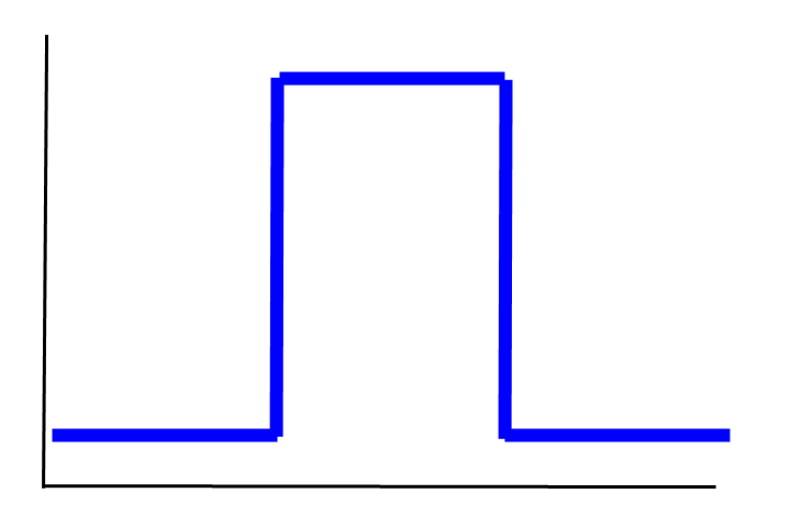
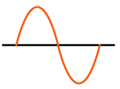
The diode D1 rectifies (clips) the AC waveform, leaving just the positive or peak, and the capacitor C1 then smooths the signal. C1 is an electrolyte capacitor and the maximum voltage it will see is 3.3 V. Frequently the circuit with D1, R1, C1 is called a peak detector.
The circuit output to the microcontroller analog input needs to be limited to 3.3 VDC. The diode D1 has a forward voltage of 1 V, so the 3.3V into it will be reduced to 2.3 V. We will solve for a gain that will cause an input of 750 V to be 2.2 V (slightly less than 2.3 V).
750 V / 2.2 V = 1,650 (desired gain)
If R6 = 5.1 M ohms, then R4 = 5.1M * 2.2/750 = 14,960 ohms or approximately 15k ohms.
The output at C1 is further smoothed with the resistor R8 and the capacitor C3 prior to amplifying the 2.2 V signal to 3.3 V (for maximum VAC input). The gain of the second op-amp used as a non-inverting amplifier is calculated as follows:
1 + R2/R7 = 3.3 V / 2.2 V = 1.50
1 + R2/R7 = 1.50
R2/R7 = 0.500
For R7 = 300k ohms, R2 = (0.500) * 300k = 150 k ohms
If the AC ground is left floating, it can produce a large DC voltage at the output of the circuit. R9 (1 W) is added to force the difference between the AC line or neutral connections be zero for the floating ground situation. The resistance of R9 is relatively low in comparison to R5 and R6. The power requirement of 1 W as calculated by:
P = E^2 / R = (530 V rms)^2 / (470 k ohms) = 0.598 W
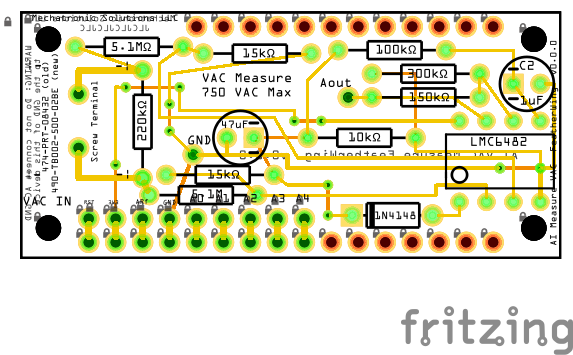
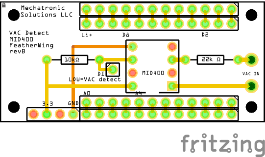
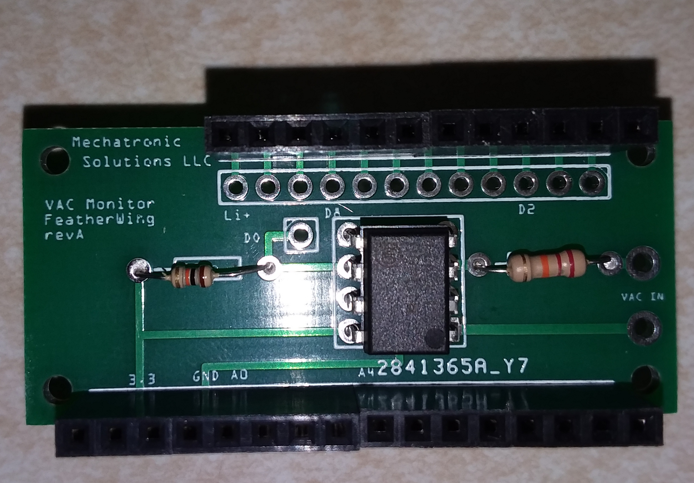
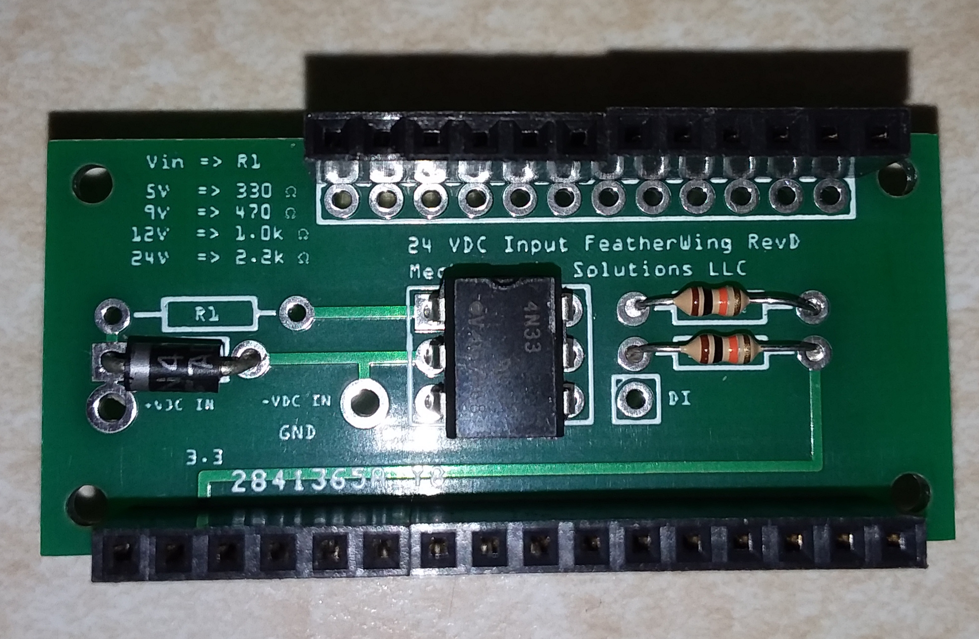
Custom FeatherWing
VAC Detect FeatherWing
Related Links
Sensor to ADC—analog interface design
TI High-Voltage Signal Conditioning for Low-Voltage ADCs
ADD HIGH VOLTAGE CAPABILITY TO THE MAX471/MAX472 HIGH-SIDE CURRENT SENSE AMPLIFIERS
Using low voltage precision op amps for a high voltage sensing application
Sensing AC voltage using microcontroller
AC Voltage measurement using PIC16F877A microcontroller (has part details)
Voltage to Current 0-5V/10V/15V to 4-20mA Isolation Transmitter Signal Converter
AC voltage sensing with 4N35 optocoupler (missing exact part number to buy)
eBay AC Voltage Sensor Module ZMPT101B 240V Voltage Transformer Module For Arduino
Low Power Contactless Voltage Sensor 100 V to 300 V with less that 5 mW power consumption. The maximum ratio error of the sensor is ±0.3% from 100 to 300 V. Link to publication
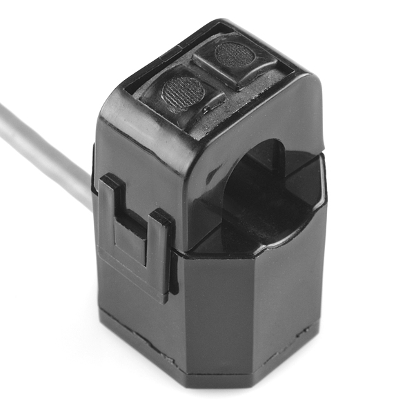
Non-Invasive AC Current Sensor - 30A
NI voltage, current, power measurement tutorial
Do you need help developing or customizing a IoT product for your needs? Send me an email requesting a free one hour phone / web share consultation.
The information presented on this website is for the author's use only. Use of this information by anyone other than the author is offered as guidelines and non-professional advice only. No liability is assumed by the author or this web site.
.png)
.png)
.png)




.jpg)














.png)

.png)
